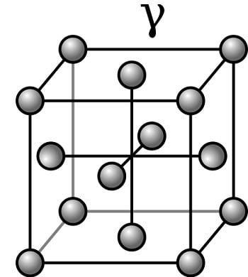
Download Diagram Fe Fe3c PDF (1300 MB) SamPDF SamPDF Muddiest Point Phase Diagrams III FeFe3C Phase Diagram Introduction This is part three in a series of screencasts about phase diagrams This video introduces major features of the FeFe3C phase diagram, steel classification, and basics applications for steelsDefinition of structures Austenite is an interstitial solid solution of Carbon dissolved in (FCC) iron Maximum solubility is % C at 1130°C High formability, most of heat treatments begin with this single phase It is normally not stable at room temperature But, under certain conditions it is possible to obtain austenite at room temperatureDiagram FeFe3C yaitu diagram yang menampilkan hubungan antara temperatur dan kandungan karbon (%C) selama pemanasan lambat Dari diagram fasa tersebut dapat diperoleh hasil yaitu berupa informasi penting yaitu antara lain 1 Fasa yang terjadi pada komposisi dan temperatur yang berbeda dengan pendinginan lambat 2
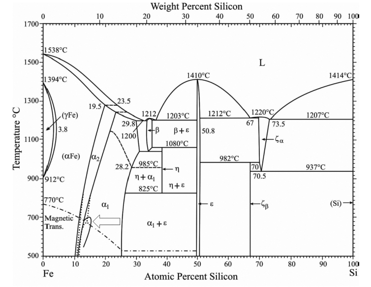
The Fe Si Phase Diagram From Electrical Steel To The Planet Mercury Center For Molecular Modeling
Fe-fe3c phase diagram explanation pdf
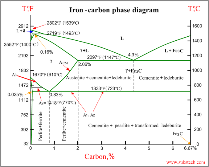
Fe-fe3c phase diagram explanation pdf- Dr Dmitri Kopeliovich Ironcarbon phase diagram describes the ironcarbon system of alloys containing up to 667% of carbon, discloses the phases compositions and their transformations occurring with the alloys during their cooling or heating Carbon content 667% corresponds to the fixed composition of the iron carbide Fe 3 C1*2/Introduction to Alloy Phase Diagrams magnesium, and manganese These substances constitute the components comprising the system and should not be confused with the various phases found within the system A system, how ever, also can consist of a single component, such as an element or compound Phase Diagrams


Iron Carbide Fe3c An Overview Sciencedirect Topics
Fe Fe3c Diagram PDF Free download as PDF File (pdf), Text File (txt) or read online for free Fefe3cdiagrampdfPhase Diagrams • Indicate phases as function of T, Co, and P • For this coursebinary systems just 2 componentsindependent variables T and Co (P = 1 atm is almost always used) • Phase Diagram for CuNi system Adapted from Fig 93(a), Callister 7e (Fig 93(a) is adapted from Phase Diagrams of Binary Nickel Alloys , P NashCementiteor iron carbide is very hard, brittle intermetallic compound of iron & carbon, as Fe3C, contains 667 % C It is the hardest structure that appears on the diagram, exact melting point unknown Its crystal structure is orthorhombic It is has low tensile strength (approx 5,000 psi), but high compressive strength
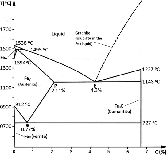
Download Free PDF FeC Phase Diagram Bogdan Chiriac Download PDF Download Full PDF Package This paper A short summary of this paper 33 Full PDFs related to this paper Read Paper FeC Phase DiagramThe ironiron carbide (FeFe3C) phase diagram Microstructures of iron α ferrite austeniteEquilibrium assumes there is more than adequate time for attaining phase chemistries and amounts of phases shown in the various fields of the diagram, and in the Fe–C system it is assumed that carbon is present as the metastable phase iron carbide, Fe 3 C, also identified by the term cementite, or as more stable graphite Cementite phase fields are defined by solid lines, graphite phase
Phase diagram has not been well establishedin the temperature, composition, and pressure ranges not related directly to iron and steel making In the present evaluation, the assessed stable FeC (graphite) and metastable FeFe3C (cementite) equilibrium phase diagrams for 0 to 25 at%Pdf in heat treatment processes of steel the very important role plays the fe fe3c phase equilibrium diagram Binary eutectics and binary eutectoids Phase diagrams are useful tools to determine the number and types of phases the wt of each phase and the composition of each phase for a given t and composition of the systemDownload Diagram Fec PDF (600 MB) SamPDF SamPDF FeC phase diagram FeC phase diagram Muddiest Point Phase Diagrams III FeFe3C Phase Diagram Introduction This is part three in a series of screencasts about phase diagrams This video introduces major features of the FeFe3C phase diagram, steel classification, and basics applications for
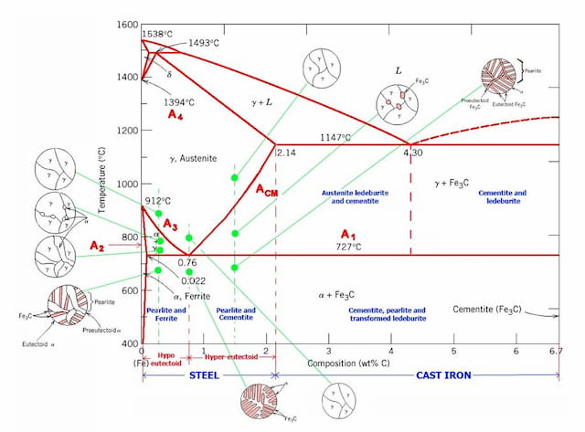


Iron Carbon Phase Diagram Explained With Graphs


Phase Diagram Industrial Metallurgists
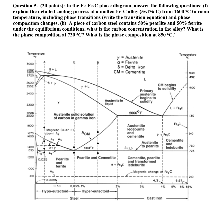
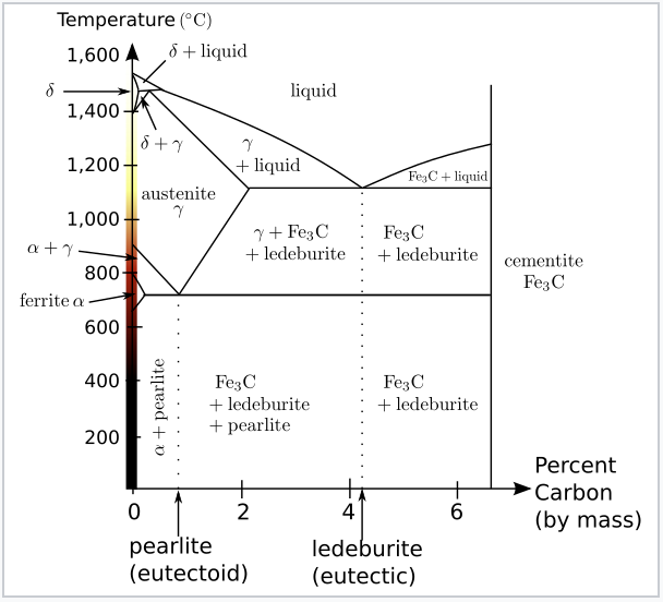
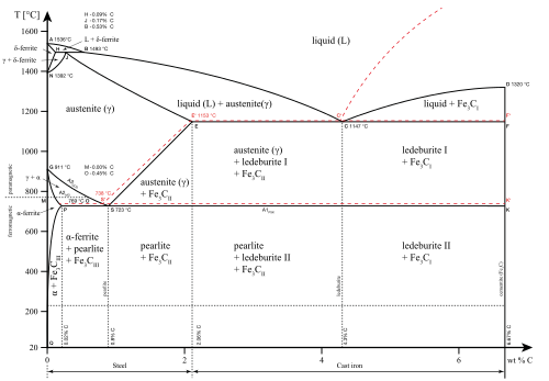
The FeFe3C phase equilibrium diagram worksheet is an important tool for understanding the microstructure and properties of carbon steel, a type of ferrous (Fe) and carbon alloy Carbon dissolves in iron in solid solution form up to 005% by weight at room temperature The ironiron carbide (FeFe3C) phase diagram Ferriteα BCC, low C solubility(0022%wt), magnetic AusteniteγFCC, high C solubility(214%wt), nonmagnetic FerriteδBCC Cementite (Fe3C) Eutectic, peritectic, eutectoid Iron, ferrite (CIron carbon diagram explanation pdf Fig 1 FeFe3C Phase Diagram (clickable), Materials Science and Metallurgy, 4th ed, Pollack, PrenticeHall, 19 Figure 1 shows the equilibrium diagram for combinations of carbon in a solid solution of iron The diagram shows iron and carbons combined to form FeFe3C at the 667%C end of the diagram


Http Courses Washington Edu Mse170 Lecture Notes Zhangf08 Lecture18 Pdf


Search Q Martensite Tbm Isch
This video introduces major features of the FeFe3C phase diagram, steel classification, and basics applications for steels Iron Carbon Equilibrium diagramThe figure above shows a typical FeFe3C phase diagram Case 1 For composition range between 0022 and 076 (Hypoeutectoid steel) When we come down from a temperature of 1000 degrees to say 600 degrees, the order of phases are math\gamma/mathMuddiest Point Phase Diagrams III FeFe3C Phase Diagram Introduction This is part three in a series of screencasts about phase diagrams This video introduces major features of the FeFe3C phase diagram, steel classification, and basics applications for steels To download the slide set from this video, visit this site
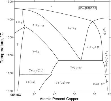


C Cu Fe Carbon Copper Iron Springerlink


1
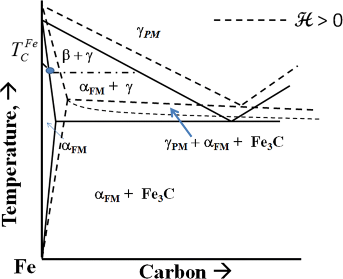
The FeFe 3 C binary phase diagram under high magnetic fields up to 21 T was investigated by a differential thermal analysis Applying a magnetic field of 18 T, the α–γ transformation temperature T α–γ for pure iron increased quadratically from 1181 K (a zero field) to 16 K With increasing magnetic field strength, the transformation temperature A c1 (αFeSurabaya, 19 September 18 Penulis f11 Pengertian Diagram Fase Diagram Fasa FeFe3C adalah diagaram yang menampilkan hubungan antara temperature dimana terjadi perubahan fasa selama proses pendinginan lambat dan pemanasan lamabat dengan kandungan karbon (%C) Diagram fasa besi dan karbida besi Fe3C ini menjadi landasan untuk laku panas(i) FeFe 3 C diagram represents behavior of steels under equilibrium conditions, whereas the actual heat treatments of steels are normally under nonequilibrium conditions (ii) The diagram does not indicate the character of transformation of austenite such as to bainite, or martensite


What Are Pro Eutectoid Phases In Fe Fe3c Phase Diagram Why Are They So Called Quora


1
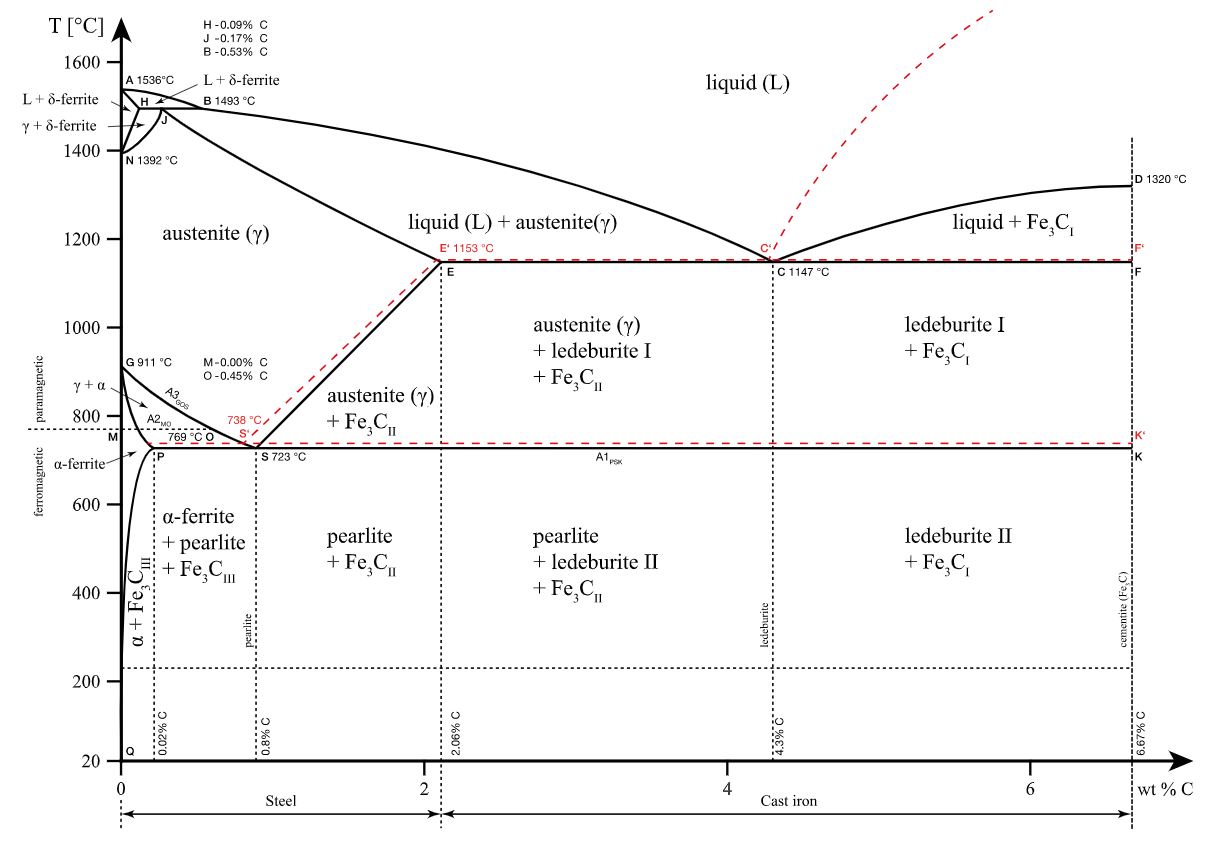
In the present evaluation, the assessed stable FeC (graphite) and metastable FeFe3C (cementite) equilibrium phase diagrams for 0 to 25 at The CFe (CarbonIron) SystempdfThe IronIron Carbide (FeFe3C) Phase Diagram Development of Microstructure in IronCarbon Alloys 946 This problem asks that we compute the mass fractions of α ferrite and cementite in pearlite The leverrule expression for ferrite is Wα = CFe 3C − C0 CFe 3C − Cα and, since CFe 3C = 670 wt% C, C0 = 076 wt% C, and Cα = 0022 wt% C Fe Fe3c Phase Diagram (Shane Cook) The percentage of carbon determines the type of the ferrous alloy iron, steel or cast iron Iron Carbon Phase Diagram The phase diagram below shows the complete ironcarbon phase diagram of the metastable system in which the carbon is present in the microstructure in the form of cementite


Iron Carbon Phase Diagram


Delta Iron An Overview Sciencedirect Topics
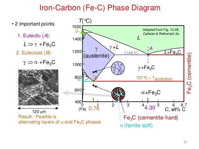
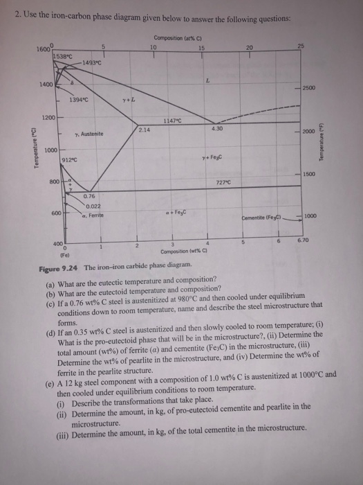
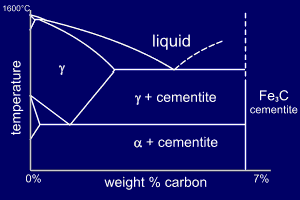
The Iron ‐ Iron Carbide (Fe‐Fe3C) Phase Diagram Reactions Phases Present Peritectic L δ = γ Lat T=1493oC and 018wt%C δ ferrite delta Eutectic L = γ Fe3C c structure at T=1147oC and 43wt%C Paramagnetic Eutectoid γ = α Fe3C γ austeniteat T=727oC and 077wt%C Fcc structure Non‐magnetic ductileMax solubility of C α ferrite Fe3C cementiteinFeFe3C TTT Diagram FeFe 3 C TTT Diagram, Adapted from Callister pg 295, Fig 106 The timetemperature transformation curves correspond to the start and finish of transformations which extend into the range of temperatures where austenite transforms to pearlite Above 550 C, austenite transforms completely to pearlite8Fe_Fe3C Phase Diagrampdf Free download as PDF File (pdf), Text File (txt) or view presentation slides online


Academic Uprm Edu Pcaceres Courses Metaleng Meng 6b Pdf
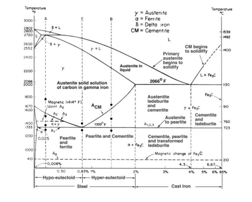


In The Fe Fe3c Phase Diagram Answer The Chegg Com
Fe Fe3c Phase Diagram Explanation Pdf Web Utk Edu Prack Mse 300 Fec Pdf Nptel Ac In Content Storage2 Courses Pdf Ppts Mts 07 M Pdf The Iron Carbon Phase Diagram Http People Virginia Edu Lz2n Mse9 Solutions Solutionshw7 Pdf Allotropes OfReview FeC phase diagram • 2 important pointsEutectoid (B) γ⇒αFe 3CEutectic (A) L ⇒γFe 3C Fe 3 C (cementite) 1600 1400 10 1000 800 600 400 0 12 3 4 5 667 L γ (austenite) γL γFe 3C αFe 3C α γ LFe 3C δ (Fe) C o, wt% C 1148°C T(°C) α 727°C = Teutectoid A R S 430 Result Pearlite = alternating layers of αand Fe 3C phases 1 μm γ γ γ R S 076 C eutectoid B FeView FeFe3C Phase diagrampdf from MM 5 at Indian Institute of Technology Indore FeFe3C Phase diagram Eutectoid Reaction Fe3C 725o C cool


Rdpalhade Files Wordpress Com 17 02 2 Iron Carbon Diagram 17 Pdf
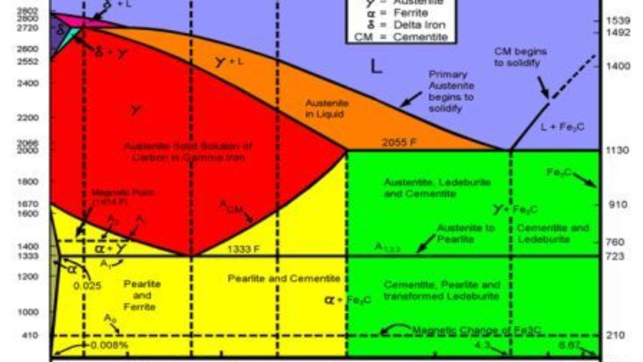


Iron Carbon Equilibrium Diagram Engineers Gallery
KEY POINTS OF FeC Diagram Phases •Liquid FeTmin=1148C @ 43%C •1394 CBINARNI DIAGRAM STANJA Fe – Fe3C Ogljik ja najvažnejši legirni element železa in je v deležu od 0 – 2,06 % Binarni diagram Fe – Fe3C Ogljik se lahko nahaja v železu v elementarni obliki, kot grafit, lahko pa je vezan z železom v železov karbid (cemntit) Na vaji smo obravnavali le levi sel diagrama – do 2,06 % C V temSystem under equilibrium is termed as phase diagram It is actually a collection of solubility limit curves It is also known as equilibrium or constitutional diagram Equilibrium phase diagrams represent the relationships between temperature, compositions and the quantities of phases at equilibrium These diagrams do not indicate the dynamics when one


Upload Wikimedia Org Wikipedia Commons 5 52 Fec Pdf
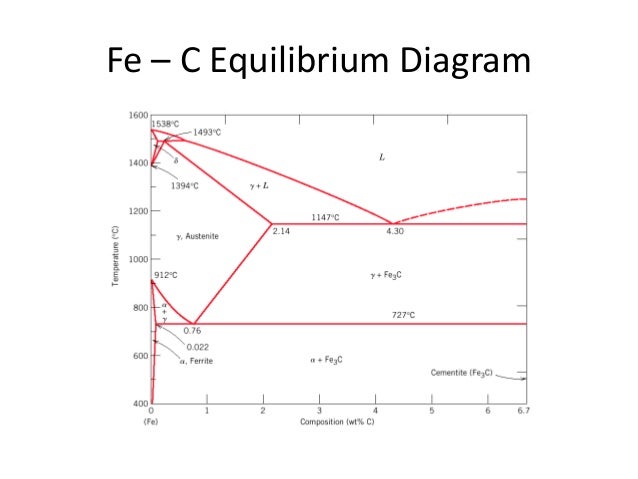


Ecc Ypnyslgcom
Figure 1233 The ironcarbon phase diagram showing the relationship between the stable irongraphite equilibria (solid lines) and the metastable ironcementite reactions (dashed lines) 5 Phases Observed in FeC Diagram • Phases 1 Ferrite 2 Austenite 3 Cementite 4 δferrite • And phase mixtures 1 Pearlite 2 Ledeburite 6 fefe3c phase diagram explanation pdf › fefe3c phase diagram microstructure › fe3c phase diagram 32 Fe3c Phase Diagram Written By Anonymous Friday, Add Comment Edit The diagram shows iron and carbons combined to form fe fe3c at the 667c end of the diagram Transforms to bcc δferrite at 1395 c is not stable below theFeFe3C PHASE DIAGRAM In their simplest form, steels are alloys of Iron (Fe) and Carbon The FeC phase diagram is a fairly complex one, but we will only consider the steel and cast iron part of the diagram, up to around 7% Carbon PDF created with pdfFactory Pro trial version wwwpdffactorycom
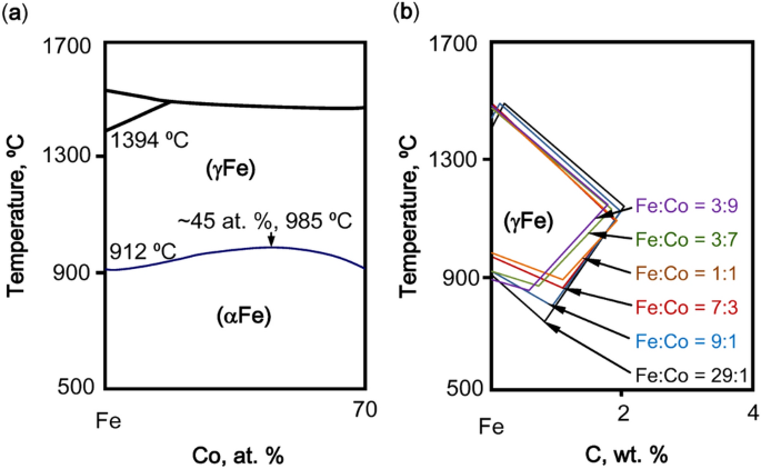


Composition Equivalents Of Stainless Steels Understood Via Gamma Stabilizing Efficiency Scientific Reports


Muddiest Point Phase Diagrams I Eutectic Calculations And Lever Rule Youtube
View FeFe3C Phase Diagrampdf from MECHANICAL 1 at Father Agnel Technical College IronIron Carbide Diagram FeFe3C Diagram Explanation of Phase fields 1Download Diagram Fe3c PDF (500 MB) SamPDF SamPDF Muddiest Point Phase Diagrams III FeFe3C Phase Diagram Introduction This is part three in a series of screencasts about phase diagrams This video introduces major features of the FeFe3C phase diagram, steel classification, and basics applications for steelsIronCarbon Phase Diagram with Detailed Explanation If the percentage of the carbon is in the range of 0 to 211 % then it is called Steel and if the percentage of carbon is in the range of 211 to 667% then it is called Cast iron As the carbon content increases, it produces more IronCarbide volume and that phase will exhibit high hardness


Http Www Hti Edu Eg Academic Files Arabic 3019 Pdf
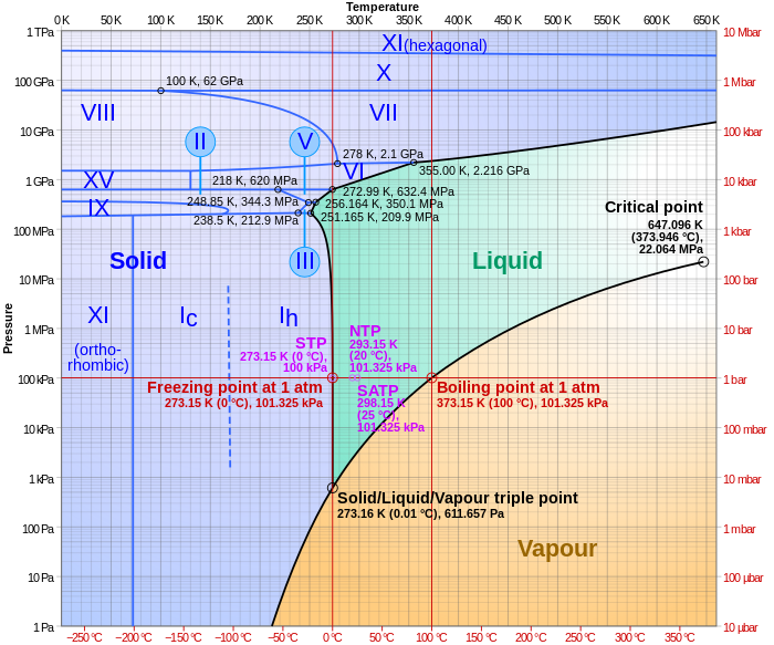


Phase Diagram Wikipedia


Fe C System Stable And Metastable Equilibrium Diagrams Springerlink


Practical Maintenance Blog Archive The Iron Iron Carbide Equilibrium Diagram


Fe Fe3c Diagram Pdf Iron Steel


Academic Uprm Edu Pcaceres Courses Metaleng Meng 6b Pdf


The Iron Iron Carbide Fe Fe3c Phase Diagram Pages 1 7 Flip Pdf Download Fliphtml5


Q Tbn And9gcqjgwnzxgnysrn5vc12dfytqlzamoopff5gvf64sdgqvbfoibrm Usqp Cau


Gate Metallurgical Engineering Iron Iron Carbide Phase Diagram


The Iron Carbide Fe Fe3c Phase Diagram Uprm Pages 1 50 Flip Pdf Download Fliphtml5


315 Phase Equilibria And Diffusion In Materials


Web Eng Fiu Edu Wangc Egn3365 9 Pdf


Iron Carbon Diagram Explanation Pdf


Steels An Introduction To Heat Treatment


The Iron Carbon Phase Diagram Ispatguru


Delta Iron An Overview Sciencedirect Topics


Cementite Wikipedia


Practical Maintenance Blog Archive The Iron Iron Carbide Equilibrium Diagram


Fe C Diagram


Phase Diagrams Book Chapter Iopscience


Cast Iron 9 5 1 General Remarks


Tpce Mech Books Iron Carbon Phase Diagram Or Equilibrium Diagram


Unary Phase Diagram E Notes 4u


Physical Metallurgy Of Ferrous Alloys Book Chapter Iopscience


Http Www Grantadesign Com Download Pdf Edupack15 Teach Yourself Phase Diagrams And Phase Transformations Pdf


Nptel Ac In Content Storage2 Courses Pdf Ppts Mts 07 M Pdf


The Iron Iron Carbide Fe Fe3c Phase Diagram Ppt Download


Http Www Hti Edu Eg Academic Files Arabic 3019 Pdf


Delta Iron An Overview Sciencedirect Topics


The Iron Carbon Phase Diagram


Mie Njit Edu Sites Mie Files Lcms Docs Me215 Module11 Revd2 Pdf


Teach Yourself Phase Diagrams


Practical Maintenance Blog Archive The Iron Iron Carbide Equilibrium Diagram


Http Www Physics Uwo Ca Lgonchar Courses P2800 Chapter8 Phasediagram Handouts Pdf


Http Nifft Ac In Writereaddata Topic 1 Pdf


The Iron Iron Carbide Fe Fe3c Phase Diagram Pages 1 7 Flip Pdf Download Fliphtml5


Iron Iron Carbide Phase Diagram Example


2 Use The Iron Carbon Phase Diagram Given Below To Chegg Com


Fe Fe3c Diagram Pdf Iron Steel


Pdf Calculation Of The Fe Fe3c Phase Equilibrium Diagram


Phase Diagrams And Pseudosections


Twip Trip Ahss Stainless Steel High Mn Steel Manganese Austenite Ultra Fine Grained Steel Ufg Steel


Http Www Gotrawama Eu Siderurgia The c Fe Carbon Iron system Pdf


Practical Maintenance Blog Archive The Iron Iron Carbide Equilibrium Diagram


Factsage Com Phase Diagram Module


Mie Njit Edu Sites Mie Files Lcms Docs Me215 Module11 Revd2 Pdf


Factsage Com Phase Diagram Module


Gate Metallurgical Engineering Iron Iron Carbide Phase Diagram


Fe Fe3c Phase Diagram Pdf Iron Iron Carbide Diagram Fe Fe3c Diagram Explanation Of Phase Fields 1 U03b1 Ferrite It Is An Interstitial Solid Solution Of Course Hero


Iron Carbide Fe3c An Overview Sciencedirect Topics


Iron Carbon Diagram Explanation Pdf


1 An Excerpt Of The Fe C Reaction Phase Diagram 68 The Right Upper Download Scientific Diagram


The Iron Carbon Phase Diagram Ispatguru


Upload Wikimedia Org Wikipedia Commons 5 52 Fec Pdf


Http Www Uobabylon Edu Iq Eprints Publication 12 15 Pdf


Iron Carbon Phase Diagram Explained With Graphs


Http Eng Modern Academy Edu Eg E Learning Mech Mnf222 printing 5 fe Carbon diagram 2 Pdf


The Iron Iron Carbide Fe Fe3c Phase The Iron Iron Carbide Fe Fe3c Phase Diagram Microstructures


Http Site Iugaza Edu Ps Jelzebda Files 10 02 Chapter09call Pdf


Http Web Itu Edu Tr Solaknu Typd Pdf


Http Www Gotrawama Eu Siderurgia The c Fe Carbon Iron system Pdf


The Fe Si Phase Diagram From Electrical Steel To The Planet Mercury Center For Molecular Modeling


Fe Fe3c Phase Diagram Powerpoint Design Templates Education Poster Mechanical Engineering


Mod 01 Lec 23 Iron Carbon Phase Diagram Youtube


Carbon Steels And The Iron Carbon Phase Diagram Ispatguru


Iron Carbon Phase Diagram Example Problem Youtube


Upload Wikimedia Org Wikipedia Commons 5 52 Fec Pdf


Fe Fe3c Phase Diagram Pdf Iron Iron Carbide Diagram Fe Fe3c Diagram Explanation Of Phase Fields 1 U03b1 Ferrite It Is An Interstitial Solid Solution Of Course Hero


Nptel Ac In Content Storage2 Courses Pdf Lecture Notes Mln 07 Pdf


Micorr


Question 5 30 Points In The Fe Fe3c Phase Chegg Com


Solidification Of Steels


Www Tcd Ie Physics People Colm Stephens Py3090 Py3090 lecture 5 Pdf


Allotropes Of Iron Wikipedia


Http Courses Washington Edu Mse170 Lecture Notes Zhangf08 Lecture18 Pdf


What Are Pro Eutectoid Phases In Fe Fe3c Phase Diagram Why Are They So Called Quora


The Iron Carbon Equilibrium Diagram Total Materia Article


Magnetic Transformations And Phase Diagrams Springerlink


7 4 Iron And Steel Chemistry Libretexts


Phase Diagram Wikiwand


The Iron Carbon Phase Diagram


Academic Uprm Edu Pcaceres Courses Metaleng Meng 6b Pdf


Metals Free Full Text Study On S Phase In Fe Al Cr Alloys Html


Solidification Of Steels


Http Www Grantadesign Com Download Pdf Edupack15 Teach Yourself Phase Diagrams And Phase Transformations Pdf


Iron Carbon Phase Diagram Substech


